

 中文简体
中文简体 русский
 Español
 عربى
عربى Português
 日本語
日本語 한국어
한국어
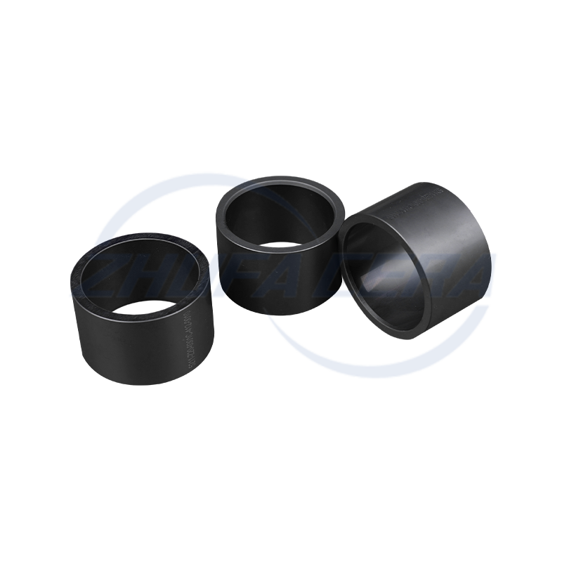
Black silicon carbide ceramic ring is a high-performance engineered ceramic assembly made of high-purity silicon carbide by precision molding and high temperature sintering. Its quadrangular crystal s...
See Details
FOLLOW US :


 Email: zf@zfcera.com
 Telephone: +86-188 8878 5188

When customizing precision ceramic structural parts, what are the common design techniques to prevent cracking and deformation?
2026-05-29
In advanced manufacturing and industrial applications, precision ceramics (such as alumina, zirconia, silicon nitride, silicon carbide) have become indispensable core materials due to their high hardness, wear resistance, high temperature resistance and corrosion resistance. However, due to the inherent high brittleness of ceramic materials and the severe volume shrinkage faced during high-temperature sintering (the shrinkage rate is usually within 15% to 25% ), the design and manufacturing of its structural parts are extremely challenging. Irrational structural design often leads to cracking, warping and deformation of products during sintering, machining or actual service.
This guide systematically summarizes the core design anti-cracking techniques, anti-deformation strategies and process matching specifications in the customization process of precision ceramic structural parts, aiming to help design engineers optimize product structure, improve yield and reduce production costs.
1. Three key points of ceramic material properties and customization
Before starting any ceramic customization project, the following three mutually restricting core elements must be examined from a global perspective.
- Material selection
The physical and chemical properties of materials determine the upper performance limit of structural parts. The following table lists the core characteristics and typical application scenarios of four mainstream precision ceramic materials.
| Material name | Core physical and chemical properties | Typical industrial application scenarios |
| Alumina | High cost performance, high hardness, wear resistance, excellent insulation, high temperature resistance (up to 1600°C above). | Electronic insulation parts, wear-resistant lining plates, ceramic substrates, vacuum chamber components. |
| Zirconia | It has the highest strength and toughness among ceramics at room temperature ( " ceramic steel " ), the thermal expansion coefficient is close to that of metal, and the thermal conductivity is low. | Fiber optic ferrules, ceramic cutters, medical implants (such as dental), plunger pump plug bodies. |
| silicon nitride | Excellent thermal shock resistance (resistance to rapid cooling and rapid heating), high strength, wear resistance, low density and small friction coefficient. | High-speed precision bearing balls, automobile engine parts, welding positioning pins. |
| silicon carbide | Extremely high hardness (second only to diamond), ultra-high thermal conductivity, excellent high temperature resistance and resistance to strong acid and alkali corrosion. | Semiconductor wafer guide rails, mechanical sealing rings, high temperature furnaces, bulletproof armor. |
- Dimensional accuracy and machining allowance
- Sintering tolerance: Directly sintered " green body " becoming " Ripe billet " Finally, due to uneven shrinkage, the tolerance can usually only be controlled within ±1% or ±0.1mm Around.
- Finishing allowance: For extremely high matching accuracy requirements (such as micron level μm ) interface must be set aside during design 15mm-0.3mm diamond grinding wheel grinding allowance.
- Molding process matching
Select the process according to the production batch and structural complexity: dry pressing is suitable for large quantities of simple flat parts; cold isostatic pressing (CIP) Suitable for large size, bar or tube blanks; ceramic injection molding (CIM) It is suitable for three-dimensional small parts with extremely complex structures, but the mold opening cost is high.
2. Core design skills for anti-cracking and anti-deformation
- Wall Thickness Design: Pursuit " absolutely uniform "
Uneven wall thickness is the number one cause of cracking in ceramic parts during sintering and cooling. The thermal expansion and contraction rates of thick parts and thin parts are different, which will generate huge internal stress.
- Avoid disparities in thickness: Try to keep the overall wall thickness consistent. If there must be thickness changes in the structure, gentle slope transitions should be used and absolutely avoided 90° of sudden changes.
- Process weight reduction holes: For heavy solid parts, blind holes, through holes or back hollowing (grooving) should be designed to reduce local thickness while ensuring mechanical strength.
- Corner design: full acute angle circle ( R angle specification)
Ceramics produced at sharp corners " stress concentration " Extremely sensitive. Sharp internal or external corners can easily become the source of cracks when subjected to thermal shock or mechanical stress.
- within / External corner radius: All corners and step transitions must be rounded. Recommend internal R angle is at least greater than 5mm (recommended R≥1.0mm ). Space permitting, R The larger the angle, the more rigid the structure.
- Assembling the corner clearing slot: If it must be retained due to the need to match metal parts 90° For external right angles, one should be designed inward at the internal corner. " Undercut " or " blind hole " , move the stress relief area away from the right angle vertex.
- Hole and edge design: Prevent sintering cracking and edge chipping
When opening holes (such as screw holes and weight-reducing holes) in ceramic parts, the position and shape of the holes have a great influence on the molding quality.
- Critical edge distance: The distance from the hole wall to the outer edge of the ceramic piece, as well as the net distance between the two holes, must be greater than the hole diameter. 5 times. Too close a distance will cause the weak area to be pulled apart at both ends during sintering shrinkage.
- Orifice chamfer: The opening edges of all through and blind vias should be designed 45°×0.3mm-0.5mm Chamfer to prevent edge chipping during subsequent grinding or actual assembly.
- Avoid shaped holes: Try to use standard round holes. Try to avoid designing long holes, square holes or special holes with sharp corners. Such holes have obvious anisotropy when shrinking and are prone to micro-cracks around them.
- Eliminate large flat surfaces: fight warping deformation
Due to the influence of gravity, friction and small differences in furnace temperature during sintering, large and thin flat parts are easily prone to warping deformation (commonly known as " Banana Bend " ).
- Set stiffeners: Designing cross-shaped, tic-shaped or radial reinforcing ribs on the back of the flat piece can significantly improve the rigidity and lock the shrinkage direction.
- Local boss design: If a certain plane needs to be used as an assembly contact surface, do not make the entire large plane into a high-precision precision contact surface. Tiny local bosses should be designed around screw holes or key fitting points, and only the surface of the bosses should be ground during subsequent finishing. This not only saves processing costs, but also effectively avoids the impact of overall plane warpage.
- Symmetrical design: balanced sintering tension
When ceramic parts are sintered in the furnace, the shrinkage force is relatively balanced in all directions. If the structure is severely asymmetrical, it will lead to unbalanced tension and overall distortion.
- Geometric symmetry: Try to make the structural parts maintain central symmetry, axis symmetry or shape symmetry on a two-dimensional or three-dimensional level.
- Craft tie (craft support beam): For asymmetric opening shapes (such as C shape, U (shaped structure), one should be artificially added to the opening during design. " Temporary process connection beam " , so that it maintains a closed-loop symmetric structure during sintering. After sintering and grinding, the temporary beam is cut off with a diamond slice.
Three. Cheat Sheet for Design Specifications of Precision Ceramic Structural Parts
The following table summarizes the wrong practices and correct specifications when designing precision ceramic structural parts for quick reference by engineers.
| design elements | Wrong approach (easy to crack / easy to deform) | Right Doing (Design for Safety, Design for Manufacturability) |
| corners and corners | Use sharp right angles ( 90° ) or extremely small rounded corners. | Enlarge the rounded corners as much as possible to design the interior and exterior R angle ( R≥0.5mm ). |
| Section wall thickness | Local sudden thickening and thinning, with no transition at the junction of thickness and thickness. | Keep the wall thickness absolutely uniform. A gentle slope transition must be used at the speed change. |
| Hole margins and spacing | Holes too close to edges or adjacent holes (spacing < aperture). | Hole margin and adjacent hole spacing ≥ 1.5 times the aperture. |
| Orifice and outer edge | The orifice has a sharp edge without chamfers. | All openings and step edge designs 45° Chamfering (preventing edge chipping). |
| Large area thin plate | Design a flat, unsupported large-area thin slab. | Design stiffeners to increase rigidity, or change to local boss contact. |
| Symmetric structure | An open structure with too long cantilevers and serious asymmetry on one side. | Maintain geometric symmetry, or introduce process support beams (removed after the blank is cooked). |
Note: During the actual project development process, it is strongly recommended to conduct manufacturing-oriented design with the ceramic forward process engineer as soon as possible after the first draft of the structural design is completed ( DFM ) review to further optimize dimensions based on the mechanical properties of the specific material.
Related products
-
-
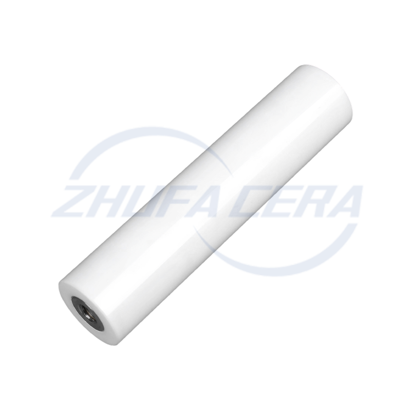
Zirconia Ceramic Rod is a high-performance ceramic material rod, mainly made of zirconium oxide, with excellent mechanical strength and chemical stability. It exhibits extremely high hardness and wear...
See Details -
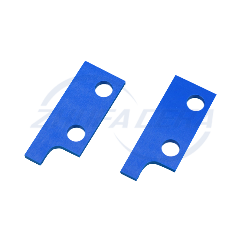
Blue zirconia ceramic sheets are precision components made of advanced zirconia ceramics. They are stained with cobalt, iron or copper to form a blue color. This color not only serves as a visual i...
See Details -
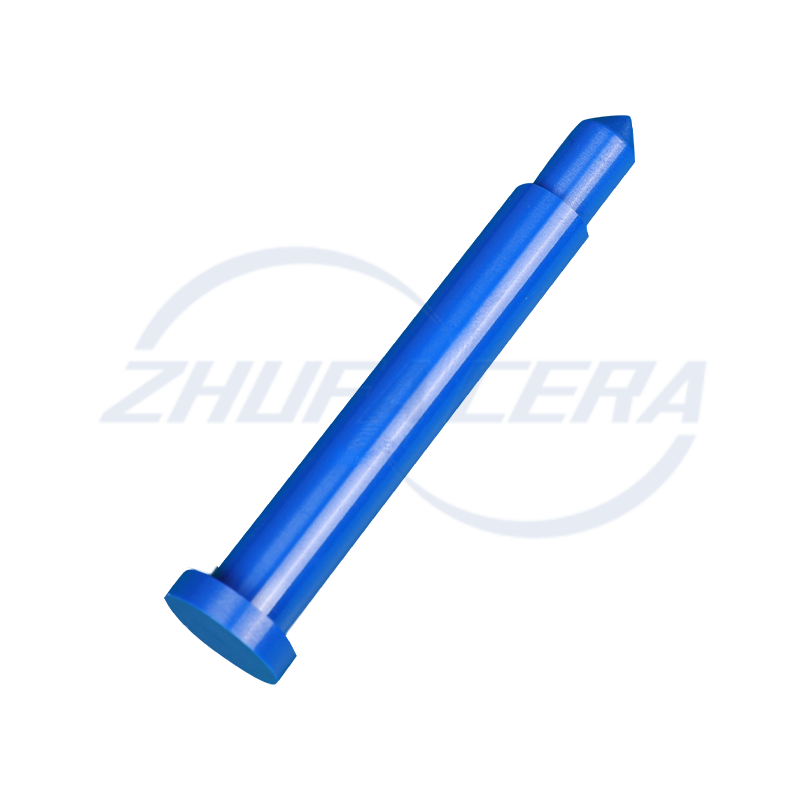
This blue zirconia ceramic pin is made of advanced zirconia ceramic material, providing excellent durability and performance. Zirconia ceramics are known for their high strength, good wear resistan...
See Details -

Zirconia Ceramic Gear is made of zirconium oxide ceramic material, which has excellent high strength and high hardness. This material property enables it to effectively resist wear during the transmis...
See Details -
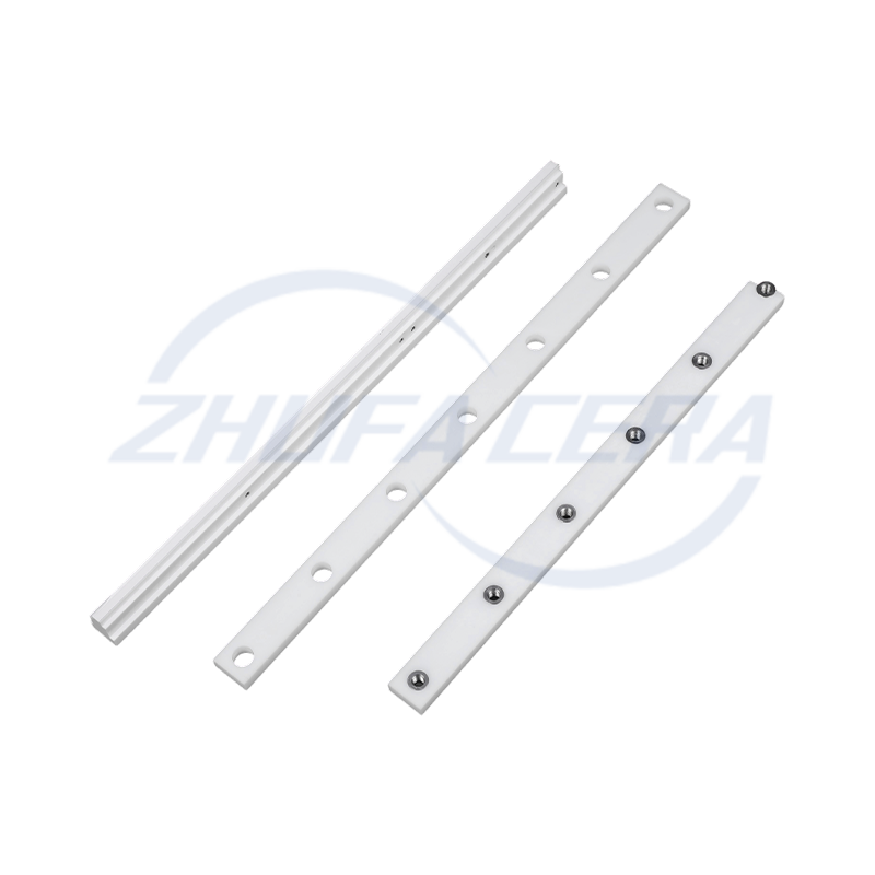
Zirconia Ceramic Guide Rail is a high-performance precision mechanical component made of zirconium oxide ceramic material. Its core characteristics are derived from the excellent physical and chemical...
See Details -
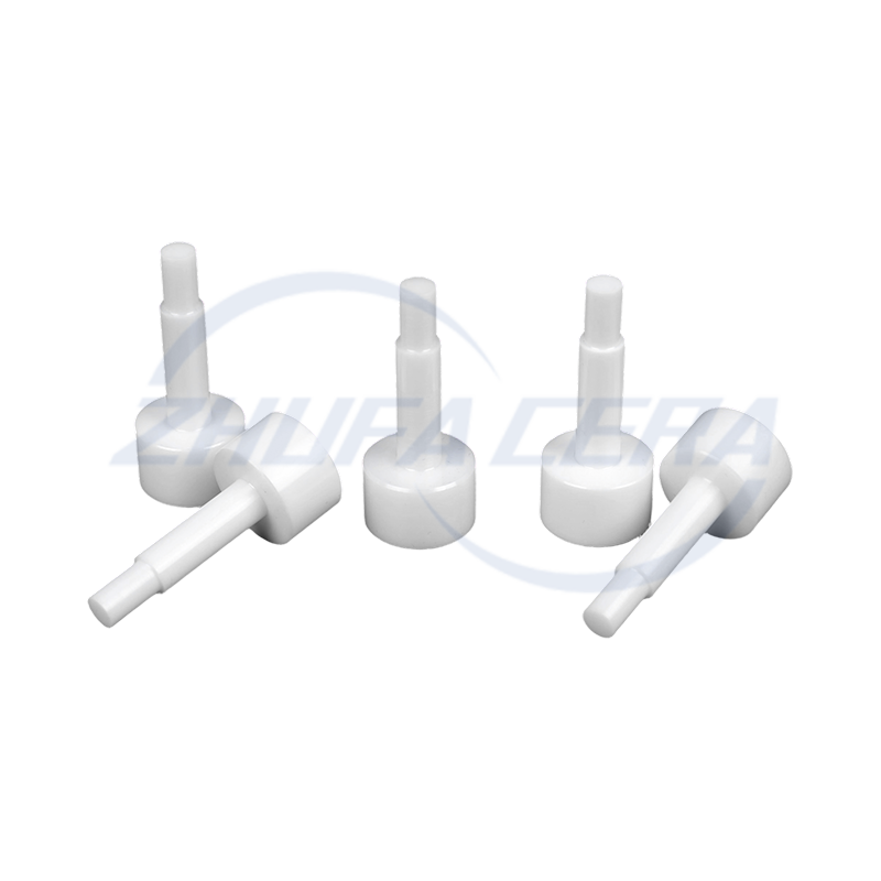
Zirconia Ceramic Locating Pin is a high-precision positioning element made of advanced zirconium oxide ceramic material with excellent physical and chemical properties. Its main characteristics includ...
See Details -
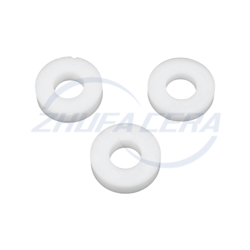
Zirconia Ceramic Ring is a high-performance ceramic product known for its excellent physical and chemical properties. It has extremely high hardness and strength, with a Mohs hardness of more than 8.5...
See Details -
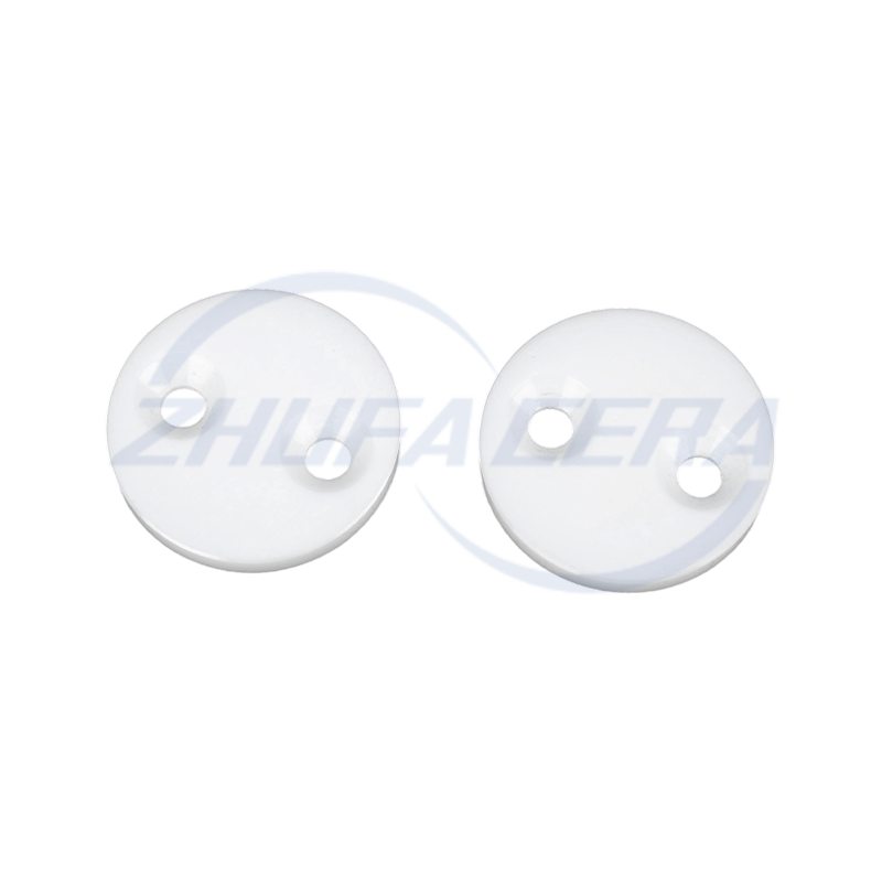
Zirconia ceramic sheets have become functional core components in various fields thanks to their unique properties. With a flexural strength of 900–1200 MPa and a fracture toughness of 6–10 MPa・m¹/², ...
See Details -
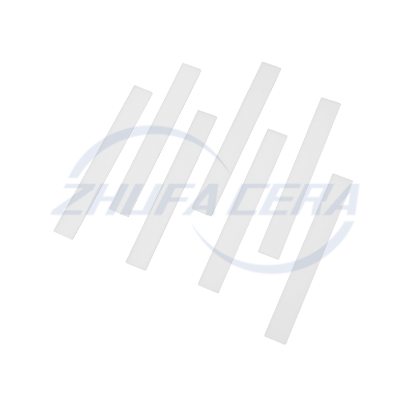
Zirconia Ceramic Strip is a strip material made of high-performance zirconium oxide ceramic with excellent physical and chemical properties. It has extremely high hardness and flexural strength, can e...
See Details -
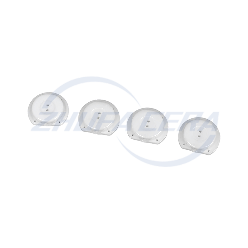
Zirconia ceramic wafers are representative products in the field of high-performance structural ceramics. Compared with traditional alumina ceramics or metal materials, its comprehensive performanc...
See Details -
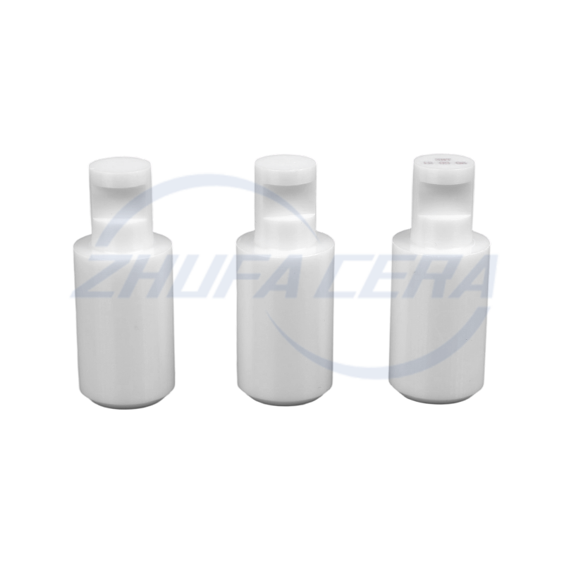
Zirconia Ceramic Plunger is a high-performance component designed for harsh industrial environments. Compared with similar ceramic or metal plunger products, it stands out with its unique material adv...
See Details


-
Quick Links
Home Products About Us Services Technology News Contact Us -
Products
Ceramic Structural Parts Zirconia Ceramics Alumina Ceramics ZTA Ceramics Silicon Nitride Ceramics Silicon Carbide Ceramics Ceramic Injection Molded Parts -
About Us
Factory Tour Honor FAQ -
Contact info
+86-188 8878 5188zf@zfcera.comNo. 1, Xinggong Road, Anchang Industrial Park, Keqiao District, Shaoxing City, Zhejiang Province, China -
WhatsApp

Copyright © Zhejiang Zhufa Precision Ceramics Technology Co., Ltd. All Rights Reserved.
China precision ceramics manufacturer
wholesale precision ceramics supplier
